Have you ever been in a building that feels cold and clammy at the same time? Or to be more specific, have you experienced what cold and humid conditions feel like? Chances are you have, hopefully not in your current home or work place, however it seems it is more likely than not.
Tighter homes and humidity challenges
As our buildings have become more energy efficient through increased insulation levels, air tight envelopes and higher SHGC windows (better windows), our homes are facing new challenges when it comes to cooling. These improved buildings have caused our cooling loads to shrink over the last decade+, and our HVAC contractors have finally been forced to rethink their air conditioner sizing policies and methodologies. The adoption of our IECC energy codes (which mandate mechanical sizing) has had a lot to do with this. This is great, because correctly sized AC’s will run longer, which helps them remove humidity. So great, problem solved, right? Ah, if only things were that simple.
Air conditioners remove two types of heat from the building:
- Sensible heat, think pure temperature rise like we measure on our thermostats
- Latent heat, think heat gain related to moisture in the air… Humidity
Air conditioners remove both types of heat, but not equally. Central air conditioners do a good job at the sensible removal; 70-80%+ , but only 20-30% of latent removal. We call this the sensible heat ratio (SHR). SHRs are typically 70-80% sensible heat removal to 20-30% latent removal.
Let’s review the 3 main components of an air conditioning system and how they impact heat removal:
- The outdoor unit, this is the part of the system that moves the refrigerant, releases heat picked up from the house to the outside, and compresses the refrigerant to a liquid.
- The evaporator coil, which is connected to your furnace/air handler, is where the refrigerant picks up heat from the house when it changes to gas, and ideally causes the air from the house to condensate as it moves over it
- The fan which blows the air over the evaporator coil from the house, and pushes the cooled air into the home.
When air conditioner systems are working correctly; the units are charged with the perfect amount of refrigerant, causing the refrigerant to change state at exactly the right time in the evaporator coil. This allows the evaporator coil to maximize the removal of water from the air in your home because it is operating at a temperature below dewpoint… meaning the coil is sufficiently cold to cause the air from the house to condense allowing the water to drain out of the house. The critical components of this process are the amount of refrigerant in the system (which must be matched to the outdoor unit’s ability to move/compress the refrigerant) and the velocity of the air over the evaporator coil.
Latent Heat is Indoor Moisture and Humidity
So here’s the problem, as mentioned cooling loads have shrunk – it’s true, but only the sensible side of the equation has gotten smaller. When it comes to latent loads, unfortunately we haven’t found a way to reduce the amount of moisture we put into the house (breathing, showers, cooking, toilettes, plants, etc…). The result is we are reducing the size of our air conditioners so they can better meet the loads, but in doing so we’re reducing the amount of latent heat/moisture they can remove, which means it’s critical the AC’s are setup correctly to maximize moisture removal. If we do not, we can end up with the buildings we started this article with – cold and humid. Worse, we can end up with homes with high moisture levels which turns into mold and ultimately does catastrophic damage to our homes.
Spoiler Alert… AC’s are often not correctly setup when installed!
When we say correctly setup, for this article we’re going to focus on airflow and fan speed (because that should be set first before the charge is checked). We’re going to focus on how well the speed of the fan in the air handler or furnace is matched to the AC.
Many of today’s industry professionals will tell you AC’s need 400 CFM of airflow per ton of cooling provided. The real answer is, like most things, it depends. It depends, largely on where the unit is installed and what the weather is like in that location. Humid climates need closer to 350 CFM/ton or less, while dry climates work just fine with 400 CFM/ton.
So given that required air flows vary from place to place, and that the same equipment is sold in Chicago, that’s sold in Phoenix or Miami; this should tell us there must be adjustments that can be made to our equipment, right?
Regardless if you’re using Carrier, Trane, American Standard, Goodman, Lennox or any other of the countless brands of HVAC equipment; there are only a handful of different fans (2 ton, 3 ton, 4 ton, 5 ton, etc…) installed in the furnaces/air handlers. These fans are matched based on the size of the furnace, which are typically sold in approx. 20kBTU increments:
- 40kBTU furnaces typically get 2 ton fans (800-900 CFM)
- 60kBTU furnaces typically get 3 ton fans (1,200-1300 CFM)
- 80kBTU furnaces typically get 4 ton fans (1,600-1700 CFM)
- 100kBTU furnaces typically get 4 or 5 ton fans (2,000+ CFM)
Priority Energy provides training and services to HVAC contractors. Because of this we have worked with thousands of HVAC contractors over the years. I used to wonder why so many of the contractors we would meet were adamant on matching specific air conditioners with specific furnaces. If we recommended a 60kBTU furnace, and a 2.5 ton air conditioner, they would frown and explain they had to put a 3 ton AC with the 60kBTU furnace or the system wouldn’t work.
Our contact with a large majority of HVAC contractors has helped us to learn that most of them:
- Are under the assumption the fan speed cannot be adjusted
- Do not know how to adjust fan speed or
- Worst case scenario, know how and why to adjust it, but simply refuse to do it when they install systems.
The HVAC contractors we know couldn’t explain why, but they knew if they put a 3 ton AC with a 60kBTU furnace they would have less problems then if they put a 2 or 2.5 ton AC with that same furnace. This was in large part because they didn’t know how to adjust the fan speed on the units.
The lesson here is that furnace manufacturers don’t know what size AC you’re pairing with their equipment, so the fan speed needs to be checked and adjusted after install to be sure the setup is correctly matched. The same advice applies to heating as well.
So How Do We Adjust Fan Speed?
There are two types of fan motors found in furnaces:
1.) PSC – The Permanent Split Capacitor Motor is still the most commonly used. They have a built in or attached capacitor that will allow the motor to turn on, turn off and run at a constant speed when running. Just because it runs at a constant speed doesn’t mean it can’t be adjusted to run at different (but constant) speeds.
2.) ECM – The Electrically Commutated Motor is becoming more common, and is definitely more efficient because of the way it runs. These are electrically controlled and can be true variable speed motors. They will turn on, ramp up slowly, and can even be set to run at infinitely different speeds depending on load and need at the thermostat/control.
Still however, the most common installation is the standard thermostat that will tell these motors to turn on based on the settings at the furnace – they will more or less run at a constant output, but can ramp up/down based on load applied.
Fan Speed on PSC Motors
PSC motors have terminals on the motors, which will allow them to run at different speeds; typically, Black = High Speed, Blue = Medium Speed, and Red = Low Speed. Some will even have Yellow = Medium Low. However you should refer to your manual, because these will vary sometimes.
These speed taps will be connected to the furnace in a variety of ways. Some furnaces will let you use a different tap for heating, cooling and fan on, others will allow different speeds for heating and cooling, and some will only allow one speed for both heating/cooling.
Our first task will be to look up the furance by model number and try to find it’s installation manual. The manual will often contain fan curves for that given furnace/blower motor combination that will tell you how many CFMs to expect at a given total of external static pressure (ESP). Visit our site – www.priorityenergy.com, if you need help with ESP – as it relates to furnaces/air handlers, we’re not psychics… although I am sensing a lot of questions coming in as I write this article. Once you’ve taken the ESP and have the fan curves you’re ready to check the connections on the board of the furnace to see what speeds are being utilized.
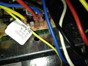
From our previous example, let’s pretend we’re looking at a 60 kBTU furnace with a 2.5 ton AC attached to it, and we’re in Chicago. We’re going to be aiming for a fan speed for cooling of approximately 350CFM/ton x 2.5 = 875 CFM. We can guess before looking at the manual, since this is a 60kBTU furnace and likely has a 3 ton blower motor in it, that it’s most likely not set correctly since the high speed terminal is being used for cooling.
However, we still need to compare the operating condtions (ESP) to the fan curves found in the manual. First note, our furance uses a red (low), blue (med-low), orange (medium-high) and black (high) wiring configuration. For our example, lets say we test the furnace while running it in cooling mode (after 10 minutes of operation) to be operating a screeching total ESP (TESP) of 0.9 iwc (not uncommon around the Chicago area, a slow death for this unit and way above the mfg recommended 0.5 iwc). Let’s look at our furnace manual. In the fan curves, for a 60kBTU furnace, in high (black) running at 0.9 iwc; this blower motor should be delivering 1,235 CFM. We’re exceeding the CFM’s we need by 1,235-875 = 360 CFM, and we’re running at 494 CFM/ton. This setup is likely causing all sorts of problems, not the least of which is higher humidity. Which means we can and should lower our fan speed by nearly 30% from where it’s at – which will have a significant impact on total ESP.
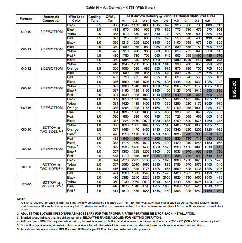
So based on our charts, if we’re aiming for 875, it would seem we should utilize the low or medium low speed setting (the red or blue wire). Since we’re starting at over 1200 CFM and we’re trying to lower it 360 CFM, I’m going to guess the TESP will decrease signficantly, so I would start with the red wire.
Fan Speed on ECM Motors
ECM motors can have the same speed taps we showed you with the PSC motors, however they often have dip switches that need to be adjusted at the board. ECM motors typically offer all the same speed adjustments as PSC’s, with the added ability to reduce speed in smaller increments from the low, medium low, medium high and high settings.
In our PSC example, we would likely have had to slow the fan speed by 7-15% to give us the ability to get much closer to our target of 350 CFM/ton.
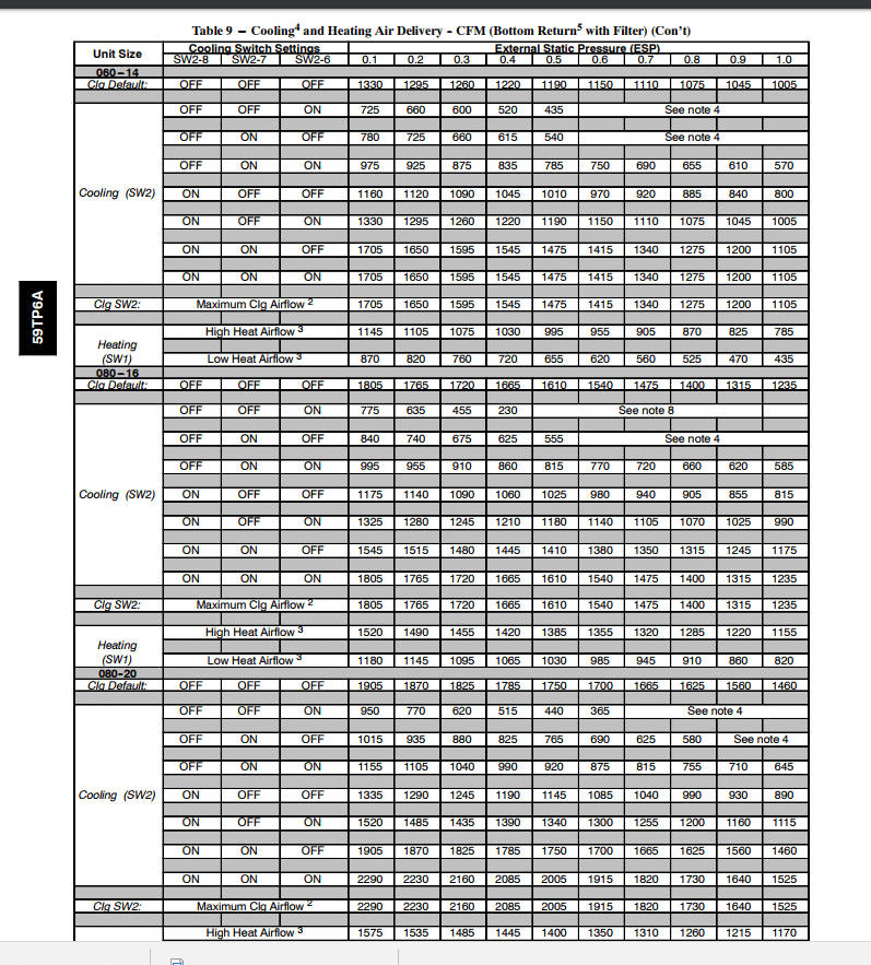
So, to check and set speed on an ECM based furnace you would need to check the TESP in cooling mode, and then refer to the manual. The manual shown here is for a Carrier furnace which utilizes dip switches for fan speed settings. Here are additional notes/adjustments which could be made on this furnace:
- Nominal 350 CFM/ton cooling airflow is delivered with SW1 —5 and SW2 —2 set to OFF.
- Set both SW1 —5 and SW2 —2 to ON for +7% airflow (nominal 370 CFM/ton).
- Set SW1 —5 to ON and SW2 —2 to OFF for +15% airflow (nominal 400 CFM/ton).
- Set SW2 —2 to ON and SW1 —5 to OFF for —7% airflow (nominal 325 CFM/ton).
The above adjustments in airflow are subject to motor horsepower range/capacity.
Fan Speed on Multi-Stage Equipment
Another adjustment that needs to be checked regarding fan speed, especially on ECM based furnaces, is related to multistage equipment. Two stage ACs and even five stage ACs are available today; however we still need to check the fan speed of these lower stages. The process is the same as above, except you’ll have another speed tap or switch setting for low stage cooling (and heating).
Additionally, many ECM based furnaces will offer one final adjustment for air speed and dehumidification. If your furnace has a port on the furnace board next to the thermostat connection terminals labeled “dehum”, this port can be used to:
- Slow the fan speed of high and low cooling when humidity is high
- Reduce the fan on time after temperature setpoints are met to minimize the amount of moisture blown back into the house from the evaporator coil.
For the dehumidification function to work, your system will need a thermostat/control that reads humidity and can energize this dehum port when the relative humidity exceeds the setpoint in the building. Examples include Honeywell’s Prestige IAQ Thermostat, and their IAQ Humidity Control. Aprilaire also makes a thermostat with humidity controls.
Finally, there is an easier way to automate all of this, which involves utilizing the manufacturer’s communicating modulating/variable speed equipment (modulating furnaces and staged/variable speed ACs/Heatpumps). All manufacturers provide the ability for the thermostat to vary heating and cooling staging and fan speed to meet temp and humidity setpoints.
In the past this functionality has been reserved for top of the line equipment, however we’ve heard rumors some of this functionality will be spreading to mid tier equipment as soon as late 2017/early 2018. We offer a word of caution though, only because we see this regularly, for this equipment to work you will need to use the manufacturer’s matching communicating controls, otherwise your modulating furnace and variable speed AC will be reduced to 2 or 3 stage equipment that could have been had for a much lower cost.
Optimizing Fan Speed Summary
For your furnace and AC to work properly, and keep humidity in check, your system first needs to be sized correctly. Second, it needs to be installed correctly, and fan speeds need to be set to deliver CFMs between 350 and 400 CFM/ton of cooling.
Finally, controls should be in place to optimize the equipment used.
Priority Energy offers builders, architects, HVAC contractors and homeowners a variety of home performance services to optimize the performance of their homes or buildings. From mechanical design to code compliance testing, we are here to support you.


